


A New Table for SeeU…
YES, YOU CAN BUILD MODELS WITH THE PMXeditor
Build Accessories and Stages with PMXE Primitives
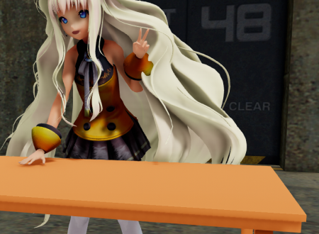
Our heroine SeeU, wanted a new table. Not being happy with the selection available at IKEA and being too snooty for Walmart, she decided to order one built specially to match her attire. Plus being a prudent buyer, she’s allocated a budget of $0.00 which means you and I will have to build it for her; especially since she wants it color coordinated with her costume.
Now the fun part for us is that we do not have to mess with a fancy 3D modeling program but build it using the PMXeditor. You could use the PMDeditor instead, but this article will specifically explain the process using the PMXeditor as it has better functionality for modeling.
We will be using the EosCustom3D translated version of the PMXeditor (ver. 0.2.2.2); a link to this version can be found in the downloads section of this site. It is not the best version honestly as some of the functions are broken but in general it will work for our purposes.
GETTING THE DIMENSIONS
Each of the squares on the grid in the PMXeditor (and MMD) are 0.5 meters (50 cm) in length. So let us load up SeeU and figure out how big our table should be and how high it needs to be.
We are going with these dimensions:
- Table top: 2m x 1m (4 x 2 grid squares)
- Table height: 1m (2 grid squares high)
CREATING THE TABLE TOP
Under the PmxView window access the Edit (E) menu and select the Primitive View (P) option. It will open the Add Simple Primitive window.

The table top is created using the Box creation option and this functionality in the PMXeditor is really nifty; it can save a ton of work. Copy our settings above or use your own. Most of them are self-explanatory but I will clarify some of the selections I made.
- By default the Physics box is unchecked. If you check the box, the PMXeditor will create a physics object for your structure. We want physics for the table top to prevent stuff like hair going through it, so this box is checked.
- Un-check the Auto Name function and enter a name for your new part. Left checked, it will use a default generic name which will not be very helpful.
- One of the quirks about the PMXeditor is how it handles measurements. 1 meter is 10, 10 cm units in the PMXeditor. So based on our desired dimensions these were the values I entered.
- Height means thickness in our case and a value of 0.2 makes this about 2 cm (about an inch) thick.
- I used a position value of 10.0 which raises the table top to a 1 meter height when it is created. By default it is built embedded into the ground plane.
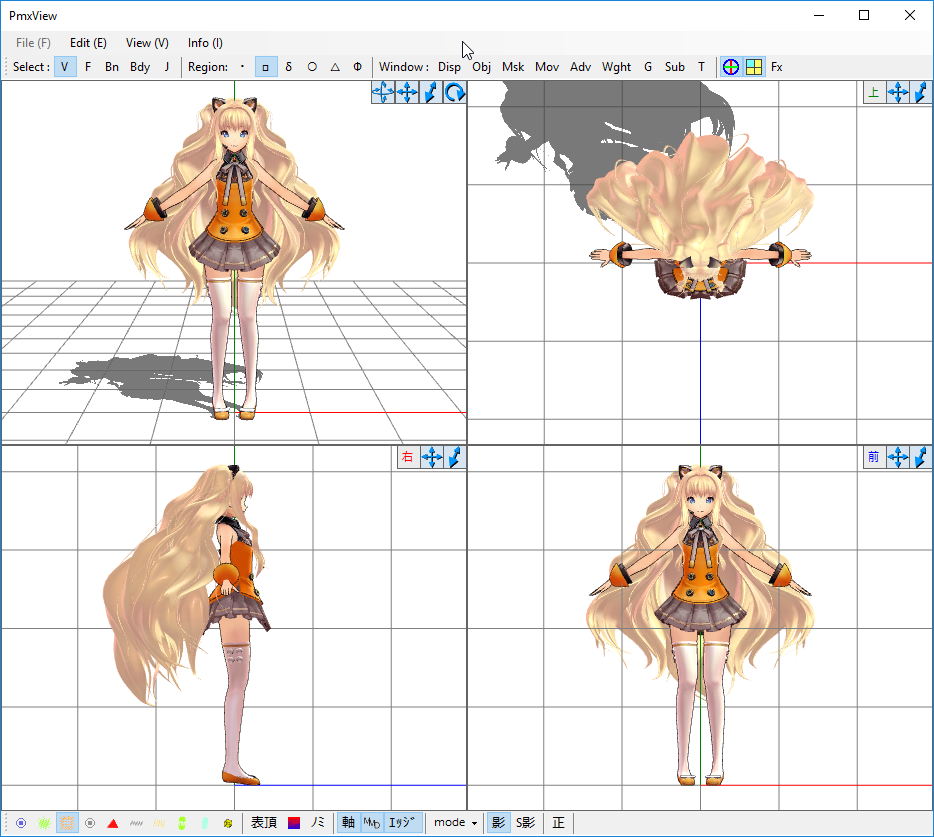
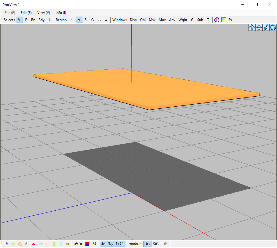
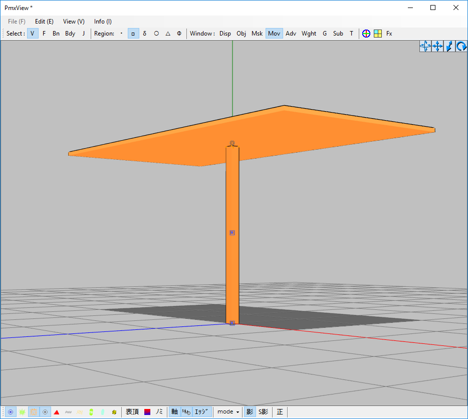
Once you click on the Add button the new part will be created and it should look as shown in the image below.
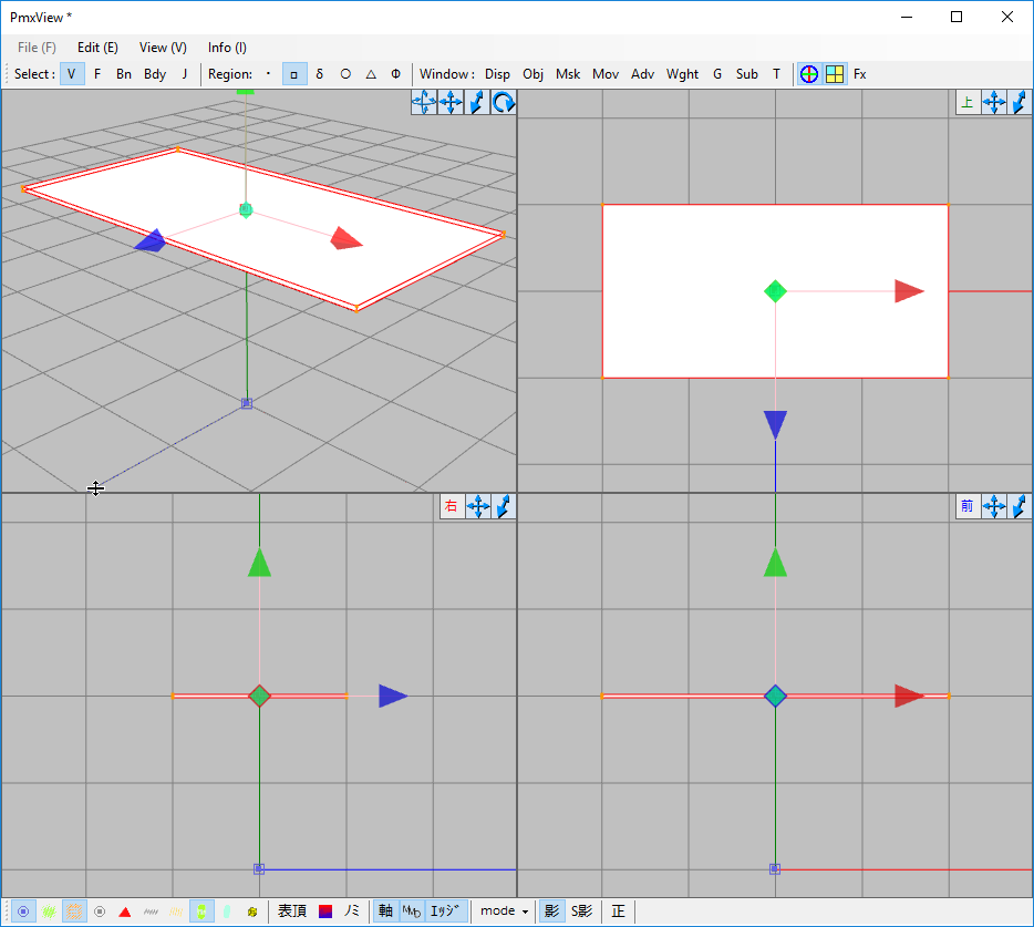
A NOTE ABOUT THE PmxView CURSOR
The PmxView cursor has multiple modes which can be accessed from a sub-menu simply by right clicking at its point of focus (the green dot in the screen above). At the moment mine is set to allow movements only, but it has other functions depending on the mode you select. Very useful once you have figured out all the modes.
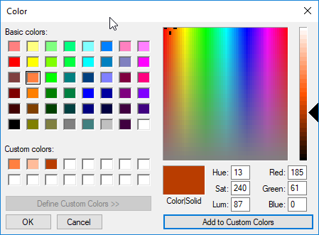
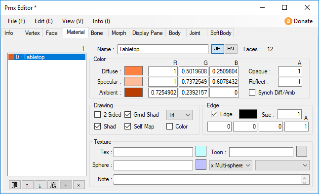
COLORING OUR TABLE TOP AND OTHER DETAILS
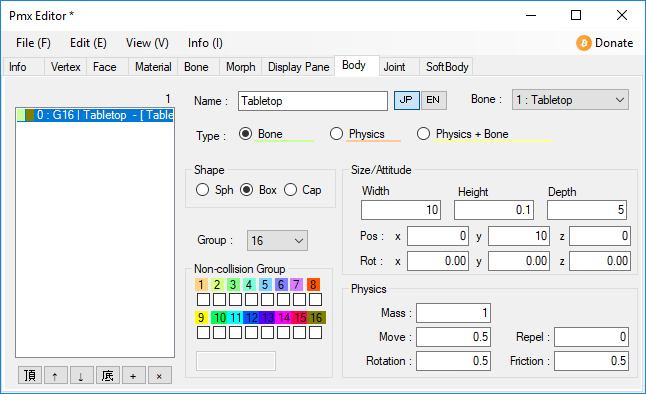
Under the Materials tab of the main Pmx Editor window, open up the Color management window. Then set your colors and then assign them to the tabletop material.
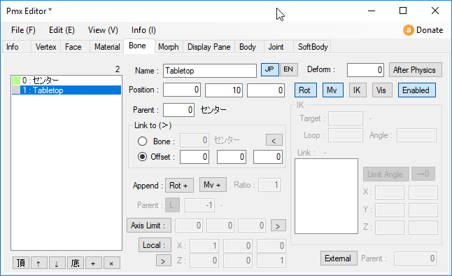
Since the Tabletop part has physics, it also has its own bone and this needs to be correctly configured. All that needs to be done is to make the bone invisible and parent it to the center bone. You do not want to allow this bone to be accessible to the user.
As for the physics, we need to configure this also as we need a static physics.
LEGS FOR OUR TABLES
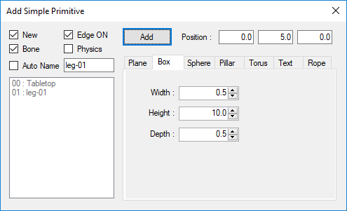
This is really easy. You only need to build a single leg and mirror it twice. First of all we will create the original leg. Note the settings used below.
- Since the leg does not need physics, we un-checked the Physics box.
- The dimensions used will make the leg 1.0 meter high and 5 cm per side.
- Note that the y-axis position is set to half a meter (5.0). This makes sure that the leg is created at the right height; otherwise it will be half underground and require manual adjustments.
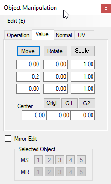
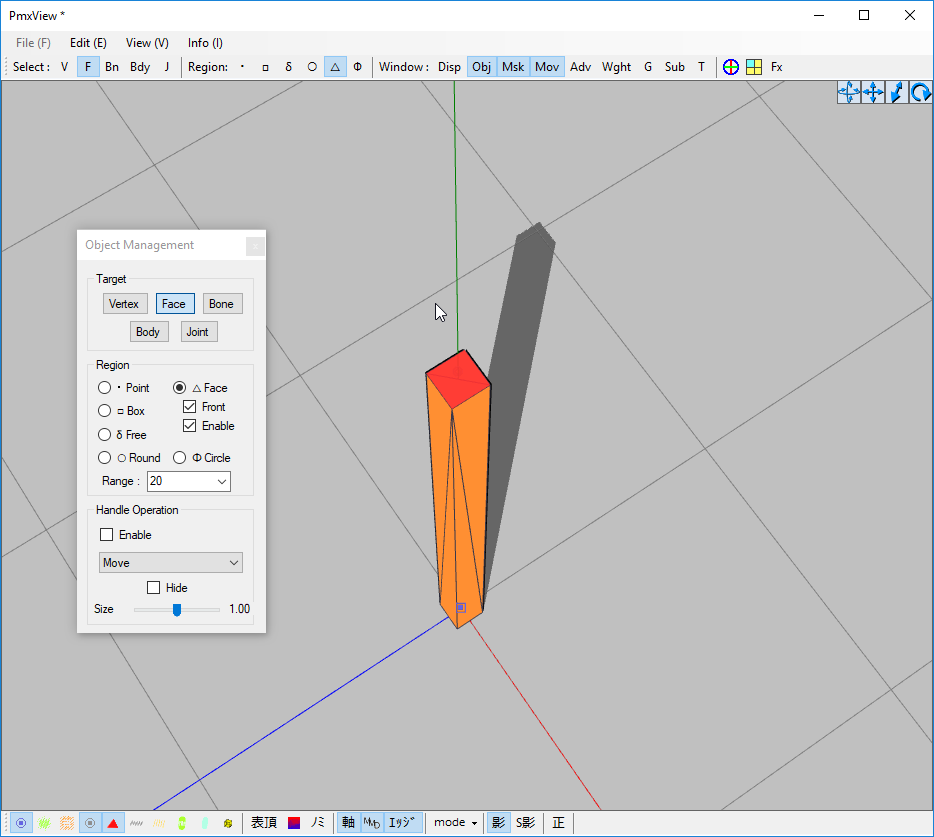
If you remember from above, our table top is 1 meter above the ground and is 2 cm thick. This means that the top portion of our leg will be touching the top surface of the table, so this needs to be corrected. Its top portion needs to be lowered by 2 cm. This is easily accomplished by selecting only the four vertices at the top of the leg and using the Object Manipulation controls we can lower these by exactly 2 cm.
At this point our leg (after specifying its colors using the procedure described above) will look as shown below. Note that it has its own bone and a top and bottom surface; all of these will need to be deleted.
Simply delete the unwanted bone from the bone list in the main PMX Editor window. The leg will not need to be re-weighted as the PMXeditor will automatically assign the weighing to the center bone.
Next change the view mode to Wire+(P) so that we can see the individual faces and turn off the display of the table top using the Vertex/Masking controls. Select the top and bottom faces and delete them.
To delete the unwanted faces use the following controls: PmxView > Edit(E) > Face (F) > Delete (D). Once you are done you can see inside the leg (it will be black).
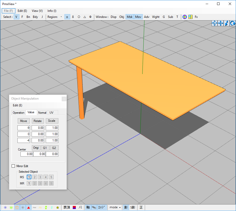
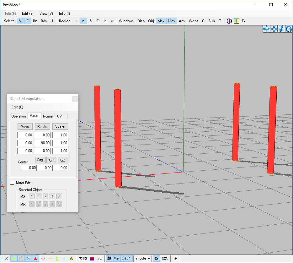
To move the leg to its final position, simply select all 8 vertices as well as all the faces that make up the leg and use the Object Manipulation panel to make the move. Note that I used the memory function (MS) on this panel to save the selection so that all I need to do is click on the MR button to re-select this particular leg. This feature works much like the memory function on most cheap calculators.
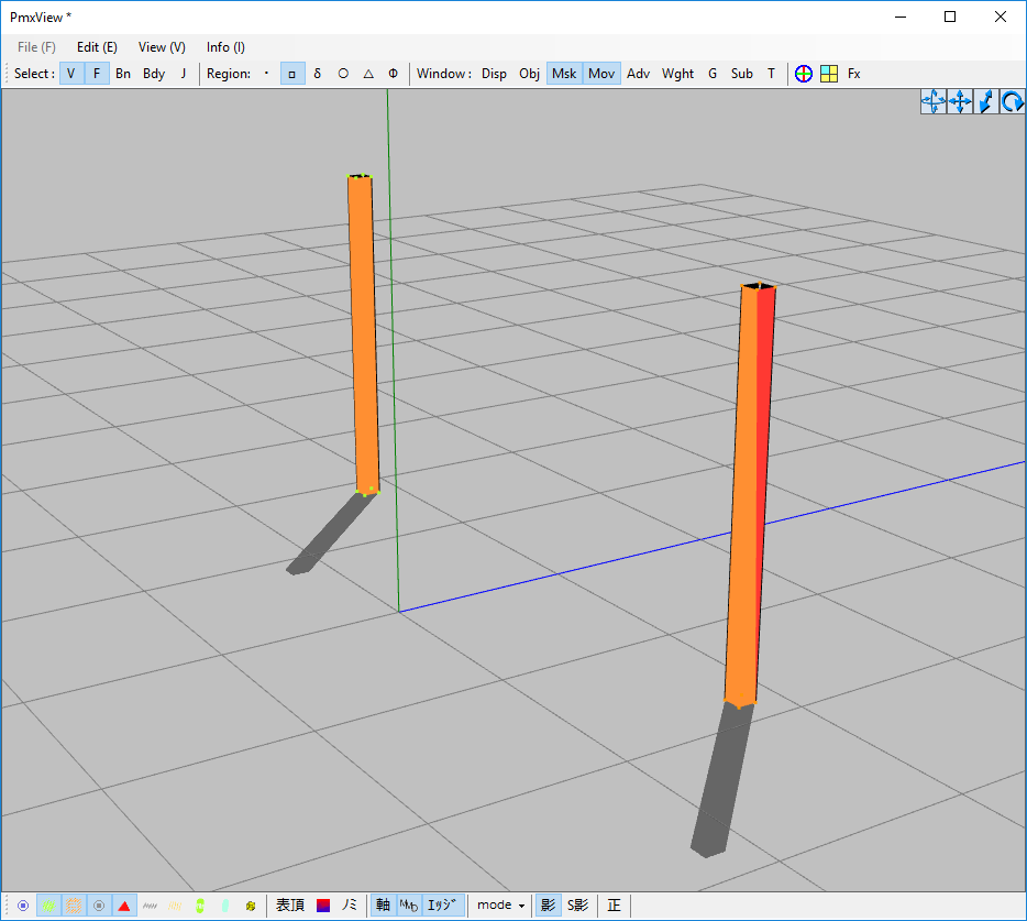
To create the next leg, select all the vertices and faces of the first leg then use the following controls: PmxView > Edit (E) > Object (O) > Mirror Object (M).
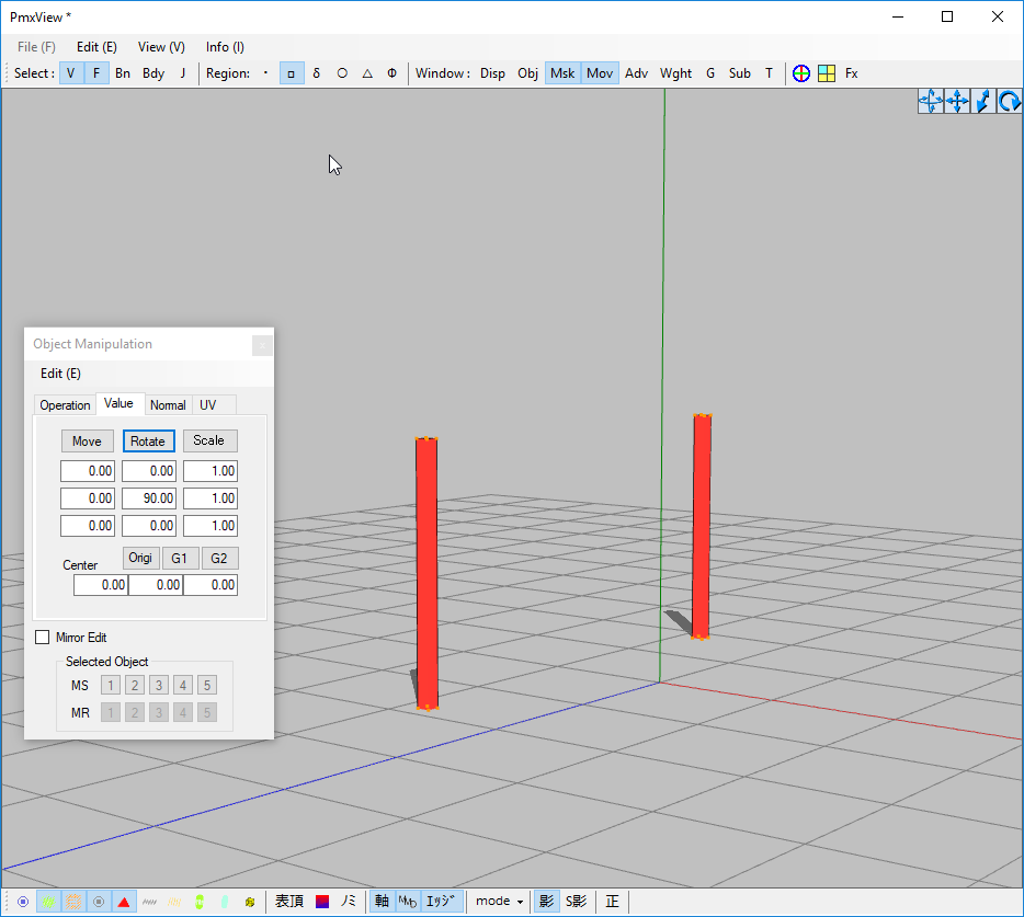
To make the other two legs we need to use a little trick as the Mirror function can be a bit buggy (or rather it has hidden dependencies). The following method is the simplest. Select both legs (vertices and faces) and rotate them 90 degrees. Use the Object Manipulation panel to do this to maintain accuracy. With the legs rotated, access the Mirror Object (M) function again and the program will create the other 2 legs; then simply select everything and rotate them 90 degrees again.
Your final table should look like the image shown below.
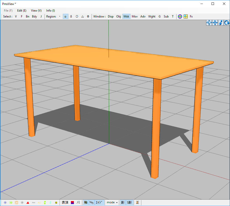
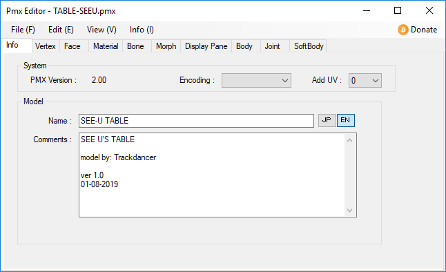
Finalize your model by creating the labeling for your table and save it in PMX format.
THE PMXeditor AS A MODELING PROGRAM
As we have shown in this article, the PMXeditor does have some powerful features that allows it to be able to be used as a viable 3D modeling program. Certainly for simple models it is very usable and in some ways a time saver. It even has smoothing functions but straight up, for more complex models, it either does not have the tools or the methodology is very convoluted. Still it is useful in a pinch or simply use it to do some quick basic modeling.
To build this table, it took me only about 15-20 mins the first time. It took a lot longer to rebuild it so that I was able to write this article.
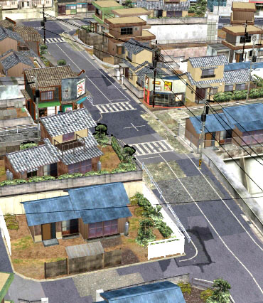
Certainly, if you really wanted to, it can be used to build an entire simple stage. For example, the original LearnMMD stage with its box like structure makes it an ideal type of design if you really want to try building a similar type of stage using the PMXeditor.
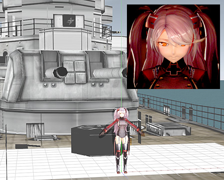
Anyway as always, thank you for reading and hopefully, you have found some useful information in this article. We will leave you one last shot of the table we were working on for this project. This time in MMD and featuring in a proper render. The table model here, is a little different from above since I refined it a bit to look more like the kitchen table that I am currently seated at while writing this article. It doesn’t look too bad for something that was done in less than 1/2 an hour.

NOTE: If you want a copy of the table as shown above it can downloaded from my Google Drive.
CREDITS
- See U – Windows100% (model by mikuxxaccelerate)
- All other models by the author
- MMD 9.31
- PMXeditor 0.2.2.2
- Ray-MMD 1.5.0
- Irfanview
- Original table design: IKEA … (the model looks “similar” only and about the same size)


I tried to rotate with 90 degree button, and i can’t make it work for some reason. Nothing happens.
Vertex and faces are enabled, ctrl+a , then 90 degree, and click the rotate… nothing.
tried in 2 different pmx editor versions.
btw it is this stage i’m trying to rotate http://fav.me/d699ae9
Well, PMXE can be counter-intuitive at times and takes some time to get accustomed to. Without seeing *how* you’re trying to do what you do, it’s hard to tell what exactly goes wrong. Can you record a video? (or at least a series of screenshots with detailed comments)
Like this https://youtu.be/xCYOXwhDwRY
Type “90” without decimal point and see if it works. If it does, check your Regional Settings for digital point/digit grouping symbols. Some of MMD and PMXE functions work incorrectly if they are set other than “familiar way”. Be cautious, though, that your *other* programs may rely on them as well (like, your works in Excel or something else may start to show rubbish if you change them), so make sure you know what you want and what you do before doing anything.
lol
IT WORKED!
Thank you very much :D
Please make a tutorial how to make a stage that is a port that fits at least 3x 300+meter German 1939-1943 warships. https://bowlroll.net/user/1458/files
“There is no royal road to geometry” — Euclid (323–283 BC)
Ptolemy I (323–283 BC) didn’t appreciate that answer either… ;)
“Some people just can’t handle the truth” — Colonel Nathan Jessup. :P
There will be a tutorial coming out soon on exactly this topic. But in the mean time, my MMD Ocean Stage (hosted on DA) is big enough to hold an aircraft carrier with escort ships.
I ‘think’ that the legs of the table actually ‘do’ need ‘physics’, or maybe i’m not knowledgeable enough of PMX editor, but when i ‘disabled’ physics on the table legs, and loaded the table in MMD , the legs would not support the table top and it would fall to the ground, when i enabled the physics of the table legs, the table would stay in it’s place.
I suspect you set up the tabletop body as “Physics” (or “Physics+Bone”) instead of just “Bone”.
Why my imported obj model are not seen in PMX Editor?
Ive changed transparency(Its called Opaque in my editor) to 1 and still are invisible.
1) Try to assign a texture to a material (must reside in the same folder) and see if the model becomes partially visible.
2) Press the “green cloud” button in the lower toolbar (make all vertices visible) and see if there are green dots outlining the silhouette of your model. If there’s none, then apparently the importing failed.
ive think must convert to pmx then
http://www.mediafire.com/file/42cp2z2qor0mlpv/item_Wooden-Cross.rar/file
OK, I see now. The problem is that when you “open” a model, PMXE assumes that textures are in the same folder where the main file is, and loads them from there. But when you “add” an object into an *empty* model, it makes no such assumptions. Even if textures are there, it just doesn’t try to search. Just save and open again, it should look all right.